

Sharing practical student projects and applied learning experiences.
DIY automatic light sensor
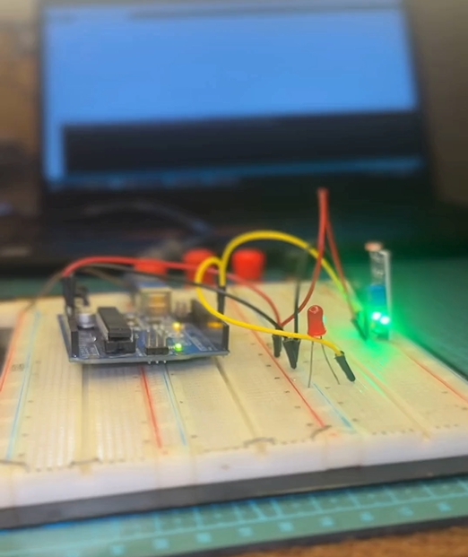
Automation projects are a great way to step into the world of electronics and microcontrollers. In this tutorial, you will learn step-by-step how to build an automatic light-detecting circuit using an Arduino Uno, a Light Dependent Resistor (LDR) module, and an LED indicator on a breadboard.
This simple DIY project is perfect for beginners who want to understand how sensors interact with microcontrollers to control output devices like LEDs or streetlights.
How It Works
The core concept behind this project is simple:
- LDR Sensor: Measures the ambient light intensity in the room. When light drops below a certain threshold (darkness), the module's signal output changes.
- Arduino Uno: Processes the signal received from the LDR module.
- LED Output: The Arduino triggers the LED to turn ON when it detects darkness and turns it OFF when there is sufficient light.
Components Required
To follow along with this build, you will need the following hardware components:
Component Quantity Description Arduino Uno1Microcontroller board LDR Module1Light sensor module with digital outputLED1Any 5mm LED (e.g., Red or Green)Breadboard1Grid breadboard for solderless connections Jumper Wires Several Male-to-Male / Male-to-Female jumper wires
Circuit Connection Step-by-Step
Follow these steps carefully to wire your circuit correctly:
Step 1: Power the Breadboard Rails
- Connect the 5V pin of the Arduino to the positive ($+$) power rail of the breadboard.
- Connect the GND pin of the Arduino to the negative ($-$) ground rail of the breadboard.
Step 2: Connect the LDR Sensor Module
- VCC Pin: Connect to the $+5\text{V}$ power rail.
- GND Pin: Connect to the ground rail.
- DO (Digital Out) Pin: Connect to Digital Pin D3 on the Arduino.
Step 3: Insert the LED
- Place the LED across two separate rows on the breadboard grid.
- Connect the Anode (+) (longer leg) to Digital Pin D2 on the Arduino.
- Connect the Cathode (-) (shorter leg) to the ground rail (or through a $220\,\Omega$ resistor to ground).
Arduino Code Example
Upload the following code to your Arduino Uno using the Arduino IDE:
C++
// Pin Definitions
const int ldrPin = 3;  // LDR Signal connected to D3
const int ledPin = 2;  // LED connected to D2

void setup() {
  pinMode(ldrPin, INPUT);
  pinMode(ledPin, OUTPUT);
}

void loop() {
  int ldrStatus = digitalRead(ldrPin);

  // If dark (LDR signal HIGH or LOW depending on module trigger)
  if (ldrStatus == HIGH) {
    digitalWrite(ledPin, HIGH); // Turn LED ON
  } else {
    digitalWrite(ledPin, LOW);  // Turn LED OFF
  }
}
Testing Your Setup
- Connect your Arduino to your computer via USB cable.
- Upload the code using the Arduino IDE.
- Cover the LDR sensor with your hand to simulate darkness.
- Result: The LED should turn ON automatically when light is blocked and turn OFF when light returns!
Conclusion
Congratulations! You have successfully built an automatic light sensor project using Arduino. This basic concept is widely used in real-world applications like automatic street lights, smart home automation, and security systems.
Have questions or want to try building this project with an analog LDR instead? Drop your comments below!
Comments (0)
No comments yet. Be the first to start the discussion.